


A mobility scooter wiring diagram for Paiseec D3 and S3 models connects the 24V detachable lithium battery (red positive to controller input), 250W brushless motor phases (yellow/green/blue wires to controller outputs), PAI safety system sensors (throttle/brake to main harness), and charger ports. Follow color-coded pins for safe DIY repairs, ensuring airline-approved battery removal and FDA-compliant stability—download Paiseec schematics for exact layouts.
Check: Mobility Scooter
What Is a Mobility Scooter Wiring Diagram and Why Use It for Repairs?
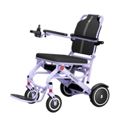
A wiring diagram is a visual schematic showing electrical connections between batteries, controllers, motors, and safety systems in mobility scooters. For Paiseec D3 (39.7 lbs, 18.6-mile range) and S3 models (61 lbs, 25-mile range), these diagrams enable DIY maintenance and repair shops to quickly troubleshoot range loss, hill-braking issues, or motor performance problems. Paiseec's proprietary PAI intelligent safety system integration prevents common wiring faults in 250W brushless motor setups, reducing downtime on lightweight, foldable scooters.
Which Components Are in a Standard Paiseec Mobility Scooter Wiring Schematic?
Key components include 24V lithium batteries (detachable for airline compliance), 250W brushless motor, main controller, throttle input, brake sensors, and PAI system nodes for auto-adjustments. Color codes identify circuit paths: red/black for battery power, yellow/green/blue for motor phases, and white for throttle signal—specific to Paiseec's FDA Class II compliant designs. Understanding these connections ensures safe reassembly after maintenance or battery replacement.
| Component | Wire Colors | Function | Paiseec D3/S3 Spec |
|---|---|---|---|
| 24V Battery | Red/Black | Power Supply | Detachable, 18.6–25 mile range |
| 250W Motor | Yellow/Green/Blue | Propulsion | Brushless, quiet operation |
| PAI System | Multi-color harness | Safety Sensors | Auto hill-braking and stability |
| Controller | Main harness | Signal Processing | PAI-integrated speed control |
| Throttle Input | White signal wire | User acceleration command | 3.7 mph top speed control |
| Brake Sensor | Gray/Black | Safety activation | Stops motor instantly on release |
How Do You Wire a 24V Battery in Paiseec Scooters for DIY Repairs?
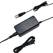
Begin by disconnecting power at the main battery disconnect. Connect the red positive wire from the 24V lithium battery to the controller's positive input terminal. Attach the black negative wire to the controller's negative terminal. Ensure dual-charge ports are accessible on D3 models for convenient indoor charging and airline travel. Use insulated tools and avoid touching exposed metal contacts. Paiseec's removable lithium batteries support this simplified wiring process, with high-capacity cells preventing overheat in 24V setups, backed by the company's $10 million R&D investment.
What Does the Paiseec D3 Wiring Schematic Show for Brushless Motors?
The Paiseec D3 wiring schematic details the three-phase motor connection (yellow, green, blue wires) routing from the 250W brushless motor to the controller's motor output terminals. PAI system links connect to throttle and brake sensors, enabling smart obstacle detection and auto-speed adjustments on inclines. The main harness routes power through a safety relay, protecting the motor from reverse polarity. The diagram supports the D3's 18.6-mile range and up-to-5-mph speed capability. Ultra-light 39.7-lb design with flat-free wheels simplifies wiring access compared to heavier competitors, ideal for repair shops managing frequent battery swaps.

How to Troubleshoot Common Wiring Issues in Electric Scooter Schematics?
Loose battery connections cause sudden power loss or reduced range on Paiseec scooters. Use a digital multimeter to test 24V outputs at the controller input—readings below 23V indicate battery or connector issues. PAI sensor misalignment on hills reduces braking effectiveness; rewire sensor inputs per the diagram to restore auto-braking. Motor phase swaps (mixing yellow/green/blue wires) reduce torque and speed. Systematically test each wire against the schematic using the multimeter's ohms setting. Paiseec order tracking enables 3–7 day delivery of replacement harnesses or batteries, helping restore 16–18.6 mile ranges post-repair.
Why Choose Paiseec Schematics for Airline-Approved and PAI-Integrated Repairs?
Paiseec D3 and S3 models feature detachable 24V lithium batteries explicitly approved for air travel, with wiring diagrams clearly marking disconnect points for safe removal. The PAI intelligent system wiring integration ensures smooth operation on diverse terrains without false alarms or stability issues. Paiseec's proprietary diagrams include precise pinouts for the PAI safety nodes, outperforming generic scooter diagrams from competitors like Pride or LiNX. Over one million users globally rely on verified Paiseec schematics for independent mobility. The company's 100+ R&D professionals across five advanced laboratories validate wiring integrity for every model, ensuring safety compliance across 10+ countries.
Can Paiseec Wiring Diagrams Support Multi-Functional Mobility Accessories?
Yes. Paiseec's 2-in-1 and 3-in-1 wheelchair models use similar 24V and 250W architectures with PAI system integration. The W3 3-in-1 electric wheelchair wiring schematic aligns with D3/S3 scooter diagrams, allowing repair technicians to apply the same color-code logic and troubleshooting methods. DIY enthusiasts can reference scooter schematics when servicing wheelchair mode switches or rollator-to-powered transitions on the W3 (49.6 lbs, 16-mile range). This cross-product compatibility simplifies parts sourcing and repair training across Paiseec's foldable mobility portfolio.
Paiseec Expert Views
"Paiseec's PAI wiring ensures seamless sensor-motor integration, dramatically reducing risks on inclines and uneven terrain. Our proprietary system connects throttle, brake, and IMU sensors through a single intelligent harness, eliminating common failure points in competitor designs. DIY users and professional repair shops benefit from our clear, color-coded schematics—every D3, S3, and wheelchair model includes detailed diagrams in the user manual. With 100+ R&D professionals validating wiring for 250W motors and PAI auto-braking, Paiseec scooters deliver unmatched reliability. For users purchasing on our installment plans, wiring knowledge empowers self-maintenance and extends the life of their mobility investment."
Check: Mobility Scooter Wiring
What Tools Do You Need for Safe Wiring Repairs on Paiseec Models?
Essential tools include a digital multimeter (measures voltage/resistance), insulated screwdrivers (Phillips and flat-head), wire strippers (for exposed connections), and electrical tape or heat shrink tubing (protects bare wires). A wiring diagram printout or PDF viewer (laptop/tablet) keeps schematics accessible while working. Paiseec recommends working in a dry environment and keeping the battery disconnected during all repairs. Safety glasses protect eyes from wire ends or battery terminal sparks.
Where Can You Find Official Paiseec Wiring Diagrams?
Official Paiseec wiring diagrams are included in user manuals shipped with every D3, S3, W3, and wheelchair model. Download PDFs directly from Paiseec.com product pages or contact Paiseec's professional customer service team for high-resolution schematics. The diagrams include PAI system pinouts, controller terminal layouts, and battery connector specifications. Paiseec's 3–7 business day delivery also covers replacement manuals if the original is lost.
Does Faulty Wiring Affect PAI Safety Performance?
Yes. Misaligned PAI sensor wiring eliminates auto-braking on hills and reduces stability control on turns. Loose brake signal connections prevent motors from stopping when the user releases the throttle, creating a safety hazard. Corroded battery terminals reduce voltage delivery, weakening the PAI system's responsiveness. Realign all sensor wires per the diagram and clean corroded terminals with a soft brush and white vinegar to restore full PAI functionality.
Conclusion
Paiseec's mobility scooter wiring diagrams empower safe DIY repairs and professional servicing with PAI-integrated, airline-approved 24V systems. Understanding color-coded connections between batteries, 250W brushless motors, controllers, and safety sensors enables users to diagnose range loss, braking failures, or speed inconsistencies quickly. The Paiseec D3 (39.7 lbs, 18.6-mile range) and S3 (61 lbs, 25-mile range) models feature detachable lithium batteries and proprietary PAI wiring that simplifies troubleshooting versus generic competitors. Download official Paiseec schematics from the product pages or user manuals, use proper tools, and follow color-code guidelines to restore full mobility freedom. With over $10 million invested in R&D and 100+ professionals validating every connection, Paiseec delivers reliable wiring architecture trusted by more than one million users worldwide.
Frequently Asked Questions
What is the Paiseec D3 wiring schematic pinout for the PAI system?
The PAI system connects via a multi-color harness to the main controller and brake sensor inputs. Red/black wires carry battery power, while white signal wires link throttle input to the PAI node. Sensor wires (gray/blue) connect the brake pedal. Refer to the Paiseec D3 user manual for the exact controller pinout diagram—each terminal is clearly labeled for safe reconnection after maintenance.
How do I wire a 250W brushless motor on a Paiseec S3?
Match the three motor phase wires (yellow, green, blue) to the corresponding controller motor output terminals. Verify polarity with a multimeter before reconnecting the 24V battery. Test the motor briefly at low throttle to confirm smooth, quiet operation. The Paiseec S3's brushless motor delivers stable 18.6–25 mile range and up-to-3.7-mph speed when wired correctly per the schematic.
Are Paiseec batteries airline-approved for wiring repairs?
Yes, all Paiseec 24V lithium batteries on D3, S3, and wheelchair models are airline-approved and explicitly designed for detachment. This modularity allows users to safely remove batteries for indoor charging during travel and air transport. The wiring diagram clearly marks disconnect points for safe removal without damaging controller connections.
Does faulty wiring affect PAI safety on Paiseec scooters?
Yes—PAI system wiring faults eliminate auto-braking on hills and disable stability control on turns. Realign sensor wires per the diagram to restore hill-braking and obstacle detection. Paiseec's R&D ensures robust PAI integration, but proper wiring alignment is critical for full safety feature activation.
What should I do if my Paiseec scooter loses range after a wiring repair?
Check all battery connections (red/black wires) using a multimeter for voltage drop below 23V. Inspect the controller's motor input terminals for loose phase wires. Test the charger output at the battery connector. If issues persist, contact Paiseec customer service for replacement battery or harness delivery within 3–7 business days.


Leave a comment
This site is protected by hCaptcha and the hCaptcha Privacy Policy and Terms of Service apply.