



![[2026] PAISEEC D3|Mobility Scooter for Easy Everyday Travel](http://www.paiseec.com/cdn/shop/files/d3_4a4ccb22-9e26-449e-8094-71f3ec4177c3.png?v=1782115044&width=180)
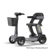










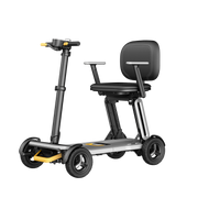
A mobility scooter wiring diagram is a visual blueprint showing electrical connections for batteries, motors, controllers, and safety sensors. For advanced smart units like the Paiseec D3 (equipped with 24V dual 6.6Ah batteries) and the long-range Paiseec S3 (powered by a heavy-duty 36V 12Ah lithium battery), understanding these schematics is essential. This technical guide explains how to read complex e-scooter layouts, decode controller wire color codes, troubleshoot PAI system wiring, and perform safe DIY repairs on lightweight folding mobility scooters.(Edited on July 5, 2026)
What Is a Mobility Scooter Wiring Diagram and Why Does It Matter?
A mobility scooter wiring diagram visually maps the electrical pathways connecting the battery pack, motor controller, throttle, and safety cut-offs. For owners of lightweight, portable scooters, wiring architecture is critical. Compact models like the Paiseec D3 (39.7 lbs) and S3 (61 lbs) endure constant mechanical stress from frequent folding, transport, and unfolding. This repetitive movement can pinch cables, loosen modular plugs, or shift highly sensitive PAI (Predictive Artificial Intelligence) sensors. Learning to read your scooter's specific blueprint allows you to isolate broken circuits, prevent complete controller burnout, and maintain structural safety without relying on expensive repair shops.
Core Component Connections & Wire Color Mappings
The central speed controller acts as the brain of the scooter, managing voltage delivery and signal distribution across all systems. While traditional scooters use basic on/off loops, standard industry color codings and proprietary smart harnesses dictate how components route to the controller.
Master Electrical Component Mapping
-
24V/36V Lithium Battery Pack: Connects via heavy-gauge wires directly to the main power terminal. The Thick Red wire routes to the positive (+) terminal, and the Thick Black wire routes to the negative (-) terminal. Systems are protected by an integrated Battery Management System (BMS) to manage cell balancing.
-
Power Lock / Key Switch / Ignition: An Orange wire (or secondary thin Red wire) that routes the main positive voltage feed directly through the physical ignition switch to energize the internal controller circuits.
-
250W Brushless DC (BLDC) Motor Phase Wires: Three distinct heavy-duty wires—Blue, Green, and Yellow—that deliver primary three-phase power directly from the controller to the hub motor for propulsion.
-
Motor Hall Sensors: A dedicated 5-wire bundled plug consisting of Red (+5V), Black (Ground), Yellow, Blue, and Green signal lines. This harness monitors real-time motor position, internal velocity, and timing alignment.
-
Smart PAI Chip & IMU Sensors: A multi-wire proprietary orange and yellow harness linking the 6-axis Inertial Measurement Unit (IMU) to the controller for automated real-time speed adjustments on steep inclines and declines.
-
Precision Throttle Control: A standardized 3-wire plug consisting of Red (+5V power feed), Black (Ground), and Green or White (Speed signal voltage return).
-
Dual Brake Levers & Cut-offs: A 2-wire or 3-wire safety switch configuration designed to ground the brake signal circuit, instantly cutting power delivery to the brushless motor the moment the mechanical brakes are engaged.
-
On-Seat Pressure Sensor: A specialized 2-wire safety switch that grounds the ignition circuit, preventing any accidental throttle activation unless an operator is securely seated.
How Does 24V vs. 36V Battery Wiring Differ in Smart Scooters?
[24V Dual Pack Setup (D3)]
[Battery A: 12V] (+) ---- (-) ==== (+) ---- (-) [Battery B: 12V]  --> Series Output to Controller

[36V Single Pack Setup (S3)]
[Single 36V 12Ah Cell Matrix Stack] ------------------------------> Heavy-Gauge Direct Harness
Voltage architecture directly determines wiring thickness, connector resilience, and power delivery logic:
24V Dual-Pack Architecture (Paiseec D3)
The 24V configuration utilizes two distinct 6.6Ah lithium battery packs wired directly in series. A heavy-gauge bridging jumper connects the positive terminal of the first pack to the negative terminal of the second pack. This series arrangement combines individual module voltages while maintaining a compact, split-weight layout optimized for airline-approved, ultra-lightweight travel frames.
36V Single-Pack Architecture (Paiseec S3)
The 36V 12Ah system relies on a single integrated lithium matrix stack. This eliminates external series bridging jumpers, simplifying the physical wiring layout. However, because higher system voltage generates greater torque and handles steeper hill climbs, the 36V architecture demands thicker phase wires, heavier-grade quick-disconnect bullet terminals, and a reinforced BMS to withstand elevated thermal spikes.
Expert Insights from the R&D Engineering Team:
"By optimizing our PAI algorithm alongside custom-tuned Battery Management Systems, we ensure absolute voltage stability across both the 24V dual-pack configurations in the D3 and the single 36V blocks in the S3. This precise firmware management prevents localized overcharging, isolates voltage drops, and extends the operational lifespan of our lightweight lithium cells well beyond 500 complete charge-discharge cycles."
Step-by-Step Guide: How to Read a Mobility Scooter Wiring Diagram Correctly
Tracing an electrical blueprint can feel overwhelming without a systematic approach. Follow this engineering-approved process to accurately read any mobility scooter schematic:
-
Locate the Primary Power Source: Start at the schematic's battery icon. Trace the thick red positive (+) line and thick black negative (-) line directly to their entry terminals on the central controller block.
-
Verify the Ignition Loop: Find the key switch or digital power lock. Identify the orange power-on signal line to confirm how battery voltage is routed to wake up the system control board.
-
Trace the Motor Drive Circuit: Identify the 3-wire high-current brushless motor circuit (Blue, Green, Yellow phase lines) running from the controller to the wheel hub. Directly adjacent, locate the 5-wire Hall sensor bundle to map position telemetry.
-
Isolate the Safety Input Loop: Trace the 2-wire seat pressure sensor harness and the 2-wire/3-wire brake lever cut-off lines. Verify that these circuits act as a primary ground interrupt for the main throttle signal line.
-
Map the Intelligent Data Bus: Locate the orange/yellow multi-wire harness connecting the integrated PAI chip and IMU sensors to ensure the intelligent algorithmic control path is fully mapped.
-
Use a Multimeter for Physical Verification: Switch your digital multimeter to the Continuity/Resistance setting. Touch the probes to both ends of a physical wire on your scooter to confirm it matches the direct path illustrated on the visual wiring chart.
Troubleshooting Common Wiring Issues in Lightweight Scooters
Lightweight, foldable mobility scooters face specific electrical vulnerabilities due to regular mechanical vibration and chassis flexing.
1. Loose Battery Connections & Terminal Oxidation
-
Symptom: The scooter cuts out completely when hitting small bumps or riding over uneven terrain.
-
Root Cause: The high-vibration environment of folding frames loosens quick-disconnect spade or bullet terminals. Exposure to ambient moisture causes micro-corrosion.
-
Solution: Disconnect the main harness, clean all metal tabs with contact cleaner or a wire brush, tighten the female slip-on connectors using needle-nosed pliers, and apply a generous layer of dielectric grease to seal out moisture.
2. Erratic Braking & PAI Sensor Alignment Shifts
-
Symptom: Sudden, unexpected deceleration or non-responsive regenerative braking assists.
-
Root Cause: The multi-wire IMU sensor harness has shifted position inside the folding neck assembly, or a pins inside the modular sensor plug have become unseated.
-
Solution: Inspect the orange/yellow wiring harness. Reseat the multi-pin modular connector until it clicks. Ensure the physical IMU sensor module is bolted perfectly flat against the chassis frame.
3. Non-Responsive Throttle (Error Codes / Voice Alerts)
-
Symptom: The display powers up fully, but twisting or pressing the throttle produces zero motor movement.
-
Root Cause: A broken ground wire (Black) or signal wire (Green/White) inside the 3-wire throttle harness, often caused by over-rotating the handlebars.
-
Solution: Set your multimeter to DC Voltage mode. Verify a steady +5V input between the Red and Black wires at the throttle plug. If +5V is present, test the signal wire while pressing the throttle; voltage should scale smoothly from 0.8V up to 4.2V. If it remains at 0V, replace the throttle assembly.
Expert Insights from the Technical Support Team:
"Advanced smart scooters feature real-time self-diagnostic systems that emit vocal alerts and specific digital error codes whenever a wiring disruption occurs. This proactive monitoring instantly safeguards the controller against catastrophic short-circuits if a wire harness becomes pinched or frayed during quick frame folding."
How to Perform Safe DIY Wiring Repairs on Your Scooter
If you need to replace a damaged wire, swap out a malfunctioning controller, or install a new wiring harness, follow these safety steps to protect your scooter’s electronic chips and maintain your factory warranty:
[SAFETY FIRST]
1. Key Off -> 2. Disconnect Main Negative (-) -> 3. Wait 5 Mins (Capacitor Discharge) -> 4. Document Connections
-
Step 1: Complete Power Isolation. Turn off the key switch and remove the ignition key. Access the battery compartment and disconnect the Thick Black Negative (-) terminal first.
-
Step 2: Discharge Residual Energy. Wait exactly 5 minutes before touching any internal controller wires. This allows the large internal capacitors inside the speed controller to safely bleed off stored high-voltage energy.
-
Step 3: Document via High-Resolution Photography. Before unplugging any component, take multiple clear photos of the wiring cluster from different angles to preserve an absolute record of wire colors, matching plugs, and routing paths.
-
Step 4: Execute Clean Splicing. When replacing a frayed wire, use marine-grade heat-shrink butt connectors or high-quality solder. Never use basic electrical tape alone, as it degrades under thermal load and structural movement.
-
Step 5: Post-Repair Testing. Reconnect the battery positive terminal, followed by the negative terminal. Elevate the drive wheels off the ground using a solid maintenance stand. Turn on the ignition and test throttle linearity, braking response, and safety sensors on a flat, controlled surface before hitting the road.
PAI Smart System Wiring vs. Traditional Mobility Scooters
Smart scooter architectures differ vastly from older, analog configurations:
| Technical Feature | Smart PAI-Enabled Architecture (e.g., S3) | Traditional Analog Scooter Layout |
| Sensor Integration | Multi-wire harness linking 6-axis IMU, on-seat pressure, and thermal probes. | Basic on/off mechanical limit switches only. |
| Braking Logic | Adaptive regenerative electronic braking managed via real-time algorithm loops. | Simple mechanical brake cables or basic electromagnetic discs. |
| System Diagnostics | Automatic voice feedback, digital error codes, and real-time BMS status logs. | None; requires manual tracing of every circuit with a multimeter. |
| Wire Harness Style | Modular, keyed, multi-pin waterproof plugs for rapid component swapping. | Universal loose spade terminals protected by plastic sleeves. |
Where to Access Official Wiring Diagrams and Support Resources
To ensure accurate repairs, always reference official, unedited technical documents:
-
Manufacturer Portals: Download model-specific schematics directly from the official product pages at Paiseec.com. These manuals include full high-resolution circuit illustrations for both the D3 and S3 editions.
-
Video Walkthroughs: Check out step-by-step visual diagnostic guides hosted on the official Paiseec YouTube channel, which demonstrate exactly how to access the controller bay without damaging structural seals.
-
Certified Repair Networks: For deep internal component damage, hardware replacement, or firmware flashing after a major controller replacement, contact authorized service technicians to ensure compliance with strict airline-safety and battery-warranty regulations.
Frequently Asked Questions (FAQs)
Can I replace a smart scooter battery myself?
Yes. Turn off the ignition, disconnect the main negative pack terminal first, and carefully follow the specific layout for your configuration (D3 24V dual packs or S3 36V single pack). Always use OEM airline-approved lithium replacements. Advanced PAI systems may require a brief power-cycle reset to calibrate the new BMS profile.
What exact voltage should a 24V system show on a digital multimeter?
A fully charged 24V dual-pack system should read between 24V and 29.4V across the combined series terminals. If the total resting voltage drops below 20V, the integrated BMS will lock down the output to prevent cell damage, indicating that individual cells need to be tested for balancing issues.
Why won't my high-performance scooter move despite having a full battery?
This is typically caused by an open safety cut-off loop. Check the 2-wire seat sensor plug to ensure it registers occupant weight, check the brake lever return springs to verify that the brake cut-off switches are not stuck open, and listen to the onboard voice alerts or check the LCD display for specific system fault codes.
Are lithium batteries wired differently to achieve official airline approval?
No. The core internal wiring layout remains identical to standard 24V or 36V electrical setups. Airline transport certification is determined strictly by individual cell chemistry, structural puncture resistance, and total watt-hour (Wh) capacity limits per pack, rather than changes to the overall electrical wiring architecture.
Can I upgrade an existing 24V mobility scooter to 36V wiring?
No, this cannot be done by simply swapping battery packs. Upgrading to a 36V power source requires a completely new 36V-rated brushless hub motor, a high-voltage speed controller, upgraded thicker wire gauges, and an updated PAI control module. Operating a native 24V system at 36V will instantly cause over-voltage burnout across your controller and safety sensors.
Leave a comment
This site is protected by hCaptcha and the hCaptcha Privacy Policy and Terms of Service apply.